Xilinx XPLDs are cool, and CoolRunner II CPLDs are fast, low-power and quite accessible. If you want to develop with them, you have a couple of options:
- Digilent Cmod-C2 ($24.99 + $9.99 shipping = $34.98)
- Dangerous Prototypes - CoolRunner-II CPLD breakout board ($12.90 + $17.03 shipping = $29.93)
- Matrix Glitcher boards from eBay (Bought 3, 3 x $3.14 + shipping = $12.76 i.e. about $4 each)
If you wonder if you can use those extra I/O terminals (shown below) somehow, note that they are not connected unless your board has the VQ44 (large) CPLD.

A second reason you might not want to use this board, is that the pins it uses don't allow you to use the global clock, reset and enable signals (GCK, GSR, GTS). This might mean some clock skew and use of extra resources, but it will likely not be noticeable for simple designs.
Unfortunately, there's not a lot of info about this board on the internet. There's only one site (in Russian) I've found, and you can find here. The schematic they have has a couple of errors (marked with blue on the schematic below), but otherwise, it was an excellent resource for me. The board I got had the CP56 package of the CPLD, so I had to reverse it anyway and make sure I know what I'm doing.

The Matrix Glitcher was made with one specific XBOX 360-specific application in mind, so you might find their design a bit weird/restrictive. In order to make it more generic and make the most out of the provided I/O pins, there are three changes you need to make, shown in red in the schematic below:
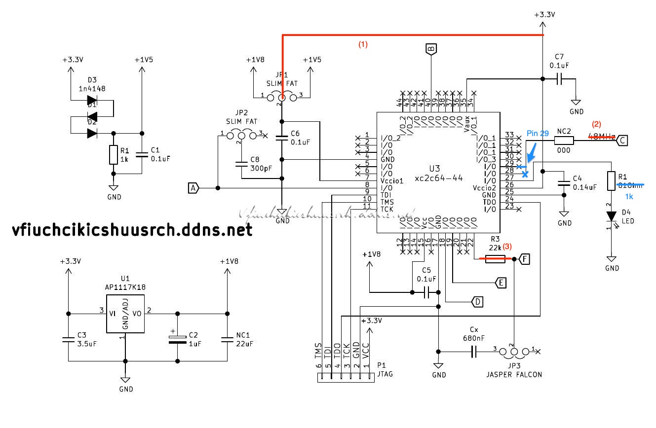

The second and third changes are a bit more tricky. By default, the 48 MHz crystal is hardwired to pin C. Assuming that you don't need that, you should disconnect it. You can do that by removing the '0' ohm resistor (2). The schematic is slightly inaccurate. Removing the '0' ohm resistor will disconnect the crystal but keep pin C connected to CPLD's Pin. Pin F is connected to the CPLD with a 22k resistor. You highly likely don't need that either. You should remove that and solder through the two endpoints (3). Alternatively, you could move the '0' ohm resistor there (I find that more stylish :)) Here is how the Matrix Glitcher looks after these two changes:

You're now ready to use the CPLD. The last thing to be aware of is that - highly likely - you don't have the VQ44/PC44 BUT, the CP56 package. This means that synthesis and the JTAG files you might create will be different to the ones for VQ44. You have to set the CP56 package explicitly in ISE WebPack. When you set constraints for your pins using the PACE Floorplan, you will have to use the CP56 pins. You can see the PIN assignments on the table below:
I/O VQ44 CP56
-----------------
A 8 H8
B 40 F3
C 29 C4
D 18 D10
E 19 E8
F 22 A10
LED 27 C5

That's all. Have fun and happy coding!

(Bottom View of XC2C64A - CP56)
Thanks. I found this as I was looking for a cheap development board and hadn't spotted that the pins were not connected. I had planned to solder directly to the surrounding pcb pads which I wrongly assumed were connected. It looks like I'll have to buy the raw chip and make my own board.
ReplyDelete